Further Development
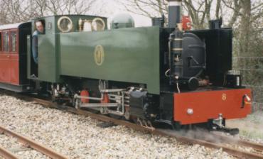
Locomotive owner Alan Richardson was so fired with enthusiasm by the success of the modifications to No. 9 that he requested a design study from Alan Keef Ltd and myself to assess what improvements could be made from a visual, functional and performance perspective to the other ZB locomotive that he then owned, BVR No. 8.
The potential for further improvement of the ZBs
No. 8, a 2-6-2T, entered service in 1997 and is styled to resemble a Vale of Rheidol tank. However, even at first sight it doesn't look quite right. The original Vale of Rheidol locomotives have a chunky charm and look as though they mean serious business while No. 8 just manages to look slab sided and plain.
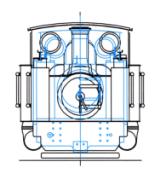
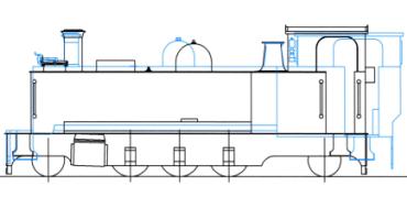
Engineer Alice Keef investigated further and after visiting the sheds at Aberystwith and carefully measuring the real thing she prepared drawings of both locomotives and overlaid them. It became apparent that No. 8 was seriously out of proportion being too long, much narrower and a bit short of height. The extra width is definitely outside the loading gauge and would cause the locomotive to seriously overhang the platform edges so this was a definite no go zone. The additional length was also a problem. The boiler couldn’t be moved forward as the firebox was already hard up against the rear driving wheels and the cab had already been lengthened by addition of a cranked back plate as engine crew were having to sit 'side saddle' to avoid toasted knees on the boiler backhead. The need for additional height was the one bit of good news. However, to completely avoid the current hunched driving stance, the cab needed to be raised further than was prototypical to the limit of the loading gauge established by No. 9.
Alice came to the conclusion that in any event the existing tanks and cabs would require replacement but, because of the constraints imposed by the BVR loading gauge, the non-scale engine crew and the current boiler and frames, it could never be made to be a good likeness. Alan was consulted about this dilemma and it was decided that the best way forward was to adopt the design philosophy of allowing form to follow function. In this way we could resolve the functional and performance issues and then consider how to make the locomotive visually attractive. As a Design Engineer I prefer this approach as otherwise the need to create a copy of a particular locomotive or type can add an additional set of constraints which may hamper achievement of the best technical outcome.
The ZB chassis and boiler arrangement is known to be rear end heavy and with the large overhang created by the firebox which is situated behind the rear drivers we knew that the weight distribution would require correction by addition of ballast at the front of the locomotive. The ride qualities of No. 8 were acceptable when running forward, which is almost always the case, but the ride in reverse was less comfortable and this was seen as an opportunity for improvement. Modification of the springing to include compensation and improvement of side control would not only improve the ride in both directions but also adhesion as the locomotive would be able to maintain traction better even on slightly uneven track. We knew from the experience with No. 9 that the additional power available meant that sanding gear was really essential and therefore it was decided to include air sanding gear for forward running.
The locomotive was constructed with oil firing because it was thought useful to have a locomotive available which would not present a fire hazard in the high summer. Originally it was supplied with a weir burner which creates a fan jet film of oil closely parallel to a similar thin but broad jet of steam which then entrains and atomises the oil. The burner was never satisfactory and after many sleeper fires with unburnt fuel flooding from the firepan the BVR developed its own design with technology similar to that used for industrial paint spray systems. In this arrangement the oil is atomised by steam as it passes through four identical nozzles which each incorporate swirl chambers. These create rotating hollow conical jets of oil which atomise as the film spreads and thins and are finally ruptured into a mass of tiny droplets. This system has proved excellent in service but is probably limiting the maximum power output of the locomotive as when it is climbing hard it tends to loose pressure and can become winded even with all four burners at maximum. In this situation the combustion is still very clean without a hint of grey and this suggests that it is running lean. Like all steam atomised systems, when the burners are at a high setting, the system generates a large quantity of very low frequency sound in the form of a continuous rumble. This has proved fatiguing for crew and can also detract from the passengers’ experience in the first few coaches if sound is reflected back into the train in cuttings.
For these reasons a change in the current firing arrangements was considered desirable to make the locomotive capable of dual fuel operation, with the options of either conventional coal firing or oil firing using a surface combustion vapourising burner. Such a burner would have a firebed of refractory 'coals' supported on a system of vapourising tubes. The gas oil is vapourised within the tubes utilising heat absorbed from the hot refractory. The refractory acts as a catalyst at high temperatures and is heated to incandescence by the combustion of the gas oil vapour on its surface. The burner could be easily installed in the same position as firebars with an oil tank provided in the bunker space. Such an arrangement would offer an oil firing system which would be kind to the boiler, by mimicking the slower thermal response characteristics of a coal fire with high radiant heat output, and provide quiet clean combustion which would be ideal for one man operation. Change over between firing methods could be made in just a few hours and would offer flexibility to use whichever fuel suited the operating or commercial situation.
Reduction of the maintenance burden and daily crew workload was considered important. Measures to achieve this would include the fitting of roller bearings in those motion items with plain bearings, such as coupling rods and little ends, and improving horn guide lubrication to reduce wear.
No. 8 has never been a very comfortable or ergonomic environment for the engine crew. It is hot, cramped, noisy and control positioning is sub-optimal. In addition it has a number of irritating quirks that can drive you crazy like the non-existent reverser scale, the lack of locker space and the rain water blowing off the top of the side tanks into the your lap!
Putting thought into cab layout and design really pays off and No. 8 would need some serious design input to bring it up to standard. No. 9 shows the way forward and is a tribute to Alice’s design skills, in fact when the Railway Inspector rode with me as part of the type approval process he commented on the excellent control layout which minimised unnecessary movement and the superb visibility.
Last, but not least, was the need to improve power output and reduce fuel and water consumption. The first step needed would be to change the cylinders and draughting as we had done for No. 9 but the cylinder diameter would be reduced slightly to maintain the tractive effort of 12.7 KN (2855 lbs) with a small increase in boiler pressure. However, given the potential scale of the rebuild we also investigated additional improvements. Moderate superheating was a logical next step and modelling of the boiler showed that a five flue superheater could provide a modest average superheat of 88° C over the operating range. Ideally it would have been good to increase this further but the restricted firebox tubeplate area available for the tube bundle prevented this. While working so extensively on the boiler the opportunity to raise the boiler pressure from 180 psi to 200 psi seemed worthwhile, offering a slight increase in efficiency for little effort except paperwork with the insurers. Similarly, doubling the thickness of the boiler insulation to 50 mm and changing from fibreglass to ceramic material would cost very little but save fuel every hour the locomotive was in steam.
Feedwater heating was also investigated. If the locomotive had been working continuously with an injector on, a straightforward option would have been to consider an exhaust steam injector. However, the switchback nature of the line means that to smooth out the demand on the boiler, most feedwater is fed when coasting down hill and so for simplicity an ‘open’ type feedwater heater with a hot well accumulation arrangement was considered the best option. With this system a gradually increasing reservoir of up to 16 gallons of water would be heated to 90° C while climbing. The heat required would be provided by condensing 14% of the exhaust steam from the cylinders in cold water drawn from the tanks. The resultant hot water could then be fed by an electric pump to the boiler under the control of the driver.
Use of the Porta Treatment system for boiler feedwater, which enables the locomotive to operate without blowdowns and very infrequent boiler washouts, was considered in detail. This process creates large quantities of suspended solids in the boiler water as a direct result of preventing scale formation. Normally this would result in foaming of the boiler water which could damage the cylinders and so the chemical treatment also includes powerful antifoaming agents to prevent water carry over. This treatment regime makes savings through extending boiler and tube life, reduces labour associated with washouts and reduces the heat losses caused by water discharge from the boiler.
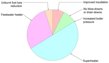
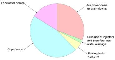
Compared to No. 9 this combination of improvements would produce further energy savings of 25% which equates to 60 Kg of coal or 46 litres (10 gallons) of gas oil and a reduction in water consumption of 46% or 922 Kg (203 gallons), broken down as shown in the charts.
Considering the 25% energy savings first, the big win is the provision of a superheater which saves 12.3% and graphically demonstrates what we all know, that this is a must have item. The next largest contribution is from the feedwater heater at 7.2%. All the other items are relatively small. Avoidance of blowdowns or drain downs saves 2.2%, improved insulation a further 1.8%, the reduction in unburnt fuel losses from reducing the carry over of fuel particles in the draught on the fire saves 1.3% and the saving from raising the boiler pressure is just 0.06%.
The possible water savings of 46% are large and once again the superheater contributes most at 21.3%, followed by avoidance of blowdowns by using the Porta Treatment at 14.3% and the feedwater heater at 7.5%. There are small savings from raising the boiler pressure of 2.4% and reduced use of the injectors and therefore water wastage of 0.9%.
The study made it clear that to bring the locomotive up to the same standard as No. 9 would require very extensive rebuilding and that to improve the thermal efficiency further would at least involve adding superheating to a boiler not ideally suited for this purpose. The limited area at the firebox tubeplate available for the tube bundle including the superheater flues, would restrict the potential superheat temperature but still necessitate complete replacement of both the firebox and smokebox tubeplates. This really represents an over development of the original design and the old adage 'if you want to go there, don’t start from here' summed up the situation.
The article continues with part six: A New Design.
