Performance Tests
After the commissioning of No. 9 it was felt that there was a lot to be gained by scientific testing of the improved locomotive and, by comparing it with Nos. 7 & 8, to see in detail what we had achieved and what could be improved further.
Dynamometer trials
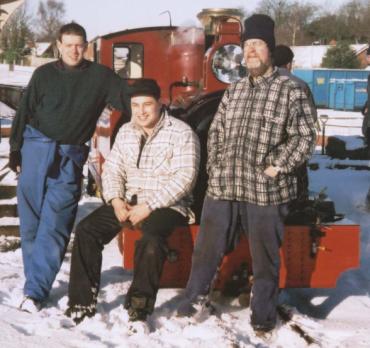
A group of engineers, John Scott, Julian Stow and Peter Mintoft, who are all volunteers on the Talyllyn Railway and had carried out instrumented trials there, kindly agreed to help us. During the spring of 2004, in two separate test sessions, they successfully recorded a mountain of data for which we are greatly indebted.
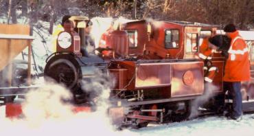
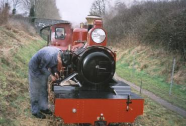
On the day of the first test it snowed, obliterating both the landscape and track which made conditions less than ideal for mounting sensitive electronic instrumentation on the locomotives! All the external electrical connectors had to be put in plastic bags and taped up to prevent short circuits and with leads held on by gaffer tape festooned everywhere, we prepared for the first trial. Pressure transducers were connected to the smokebox, to measure the vacuum, and sequentially to both the front and rear cylinder drain cock ports, to measure the cylinder pressure continuously. A linear transducer coupled to the crosshead, simultaneously recorded the cylinder position and a special coupling, containing a strain gauge, enabled us to record drawbar pull.
The mass of data produced by these instruments had to be recorded and so the coach adjacent to the locomotive became the temporary dynamometer car for the test engineers with a data logger plus two computers to input run details and view the results. Power for this equipment was supplied by a portable generator further back down the train and the same 26 Tonnes set comprised of eleven carriages plus a generator car and a guards van was used for all the tests. Each locomotive was tested in turn with BVR chairman and driver Andy Barnes on the footplate assisted by Bob King and Patrick Keef acting as firemen. We used the nearest long bank close to Aylsham to provide something for the loco to work against and after accelerating the train down the bank from Burgh summit to a specified speed at the foot of the bank at Mermaid under bridge we then attempted to maintain a constant speed up the 1:110 bank towards Brampton. The locomotives were driven with a wide open regulator and the speed was controlled during the climb by adjusting the cut-off.
During the first series of tests each locomotive made numerous runs at different set speeds. Because we only had one high temperature pressure transducer, readings were taken of cylinder pressure at the front and rear drain cock ports on separate runs which meant that we had to do two trips to gather all the data.
The purpose of the trials was to establish a series of performance parameters which could be used to compare each of the locomotives. The tractive effort measured at the drawbar in kilonewtons (KN) at a measured speed enables the power output to be calculated in drawbar horse power (dhp). The indicator diagrams enable the cylinder efficiency in terms of extracting work from the steam to be compared. The cut-off setting from the diagram shows the amount of expansion of the steam occurring in the cylinder, the lower the % the greater the expansion. The exhaust backpressure is a measure of the negative work being done to force the steam from the cylinders via the valves and through the blast nozzle. The higher the back pressure in pounds per square inch (psi) the more wasted energy. The smokebox vacuum which is expressed in mm of mercury (Hg) determines the amount of draught available to burn the fuel. An efficient exhaust system creates enough draught to burn sufficient fuel for the steam required but does so at the lowest possible back pressure.
Trial results
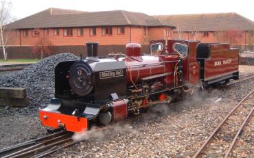
The first locomotive to be tested was No. 7, the second of the ZB class of locomotives, built in 1994 and subsequently modified by the BVR to include improved valves. With the exhaust sounding as impressive as ever, the locomotive achieved a maximum power of 35.6 dhp at a steady speed of 11.9 mph generating a drawbar pull of 5 KN (1123 lbs) at between 55-60% cut-off. The smokebox vacuum was -11 mm Hg but the average backpressure at the cylinder was a woeful 65 psi, more than 43% of the boiler pressure of 150 psi and clearly one of the reasons for the deafening exhaust roar. The cylinder indicator diagrams show a severe lack of lead steam probably due to port and passageway restrictions which meant that steam had difficulty filling the cylinder adequately at the start of each stroke.
Next up was No. 8, the third member of the ZB class which entered service in 1997 and is mechanically similar to No. 7 though it is styled to resemble a Vale of Rheidol tank locomotive and is oil rather than coal fired. Despite generating insufficient steam to maintain boiler pressure which fell from 165 to 140 psi during the test a peak power output of 40.1 dhp was recorded. This was achieved at 55% cut-off at 13.4 mph generating a drawbar pull of 5 KN (1123 lbs), exactly the same as No.7. However, the average back pressure was lower at 43.5 psi or around 28% of the boiler pressure. This better result is probably due to the slightly larger passageway sizes in the cylinders and this seemed to be confirmed by the indicator diagrams which show an improved but still poor lead steam event. Given the reluctant steaming of this loco it is possibly significant that the smokebox vacuum was lower than No. 7 at -7mm Hg. However, it may be limited by the oil burner output as it is not possible to generate even a hint of grey in the exhaust at maximum evaporation rates which suggests that more fuel could be usefully burnt in the available air.
Finally it was the turn of No. 9 and with the significant improvements that had been made to the cylinders, valve gear and draughting we awaited what we hoped to be an interesting result with considerable excitement. With everyone on board we set off down hill accelerating towards test speed with Patrick Keef reporting on a two way radio the boiler pressure, steam chest pressure and cut-off at frequent intervals. At first all was going well and with speed picking up fast we all confidently expected an outstanding performance during the climb from Mermaid. However, as Andy Barnes started lengthening the cut-off the eager faces leaning out of the windows were abruptly treated to a deluge of black rain as the boiler contents suddenly foamed. Andy immediately shut off, opened the drain cocks and tried opening up again gently but once again, as Andy demanded some serious work, the contents foamed violently. Even though we made several runs, we were unable to achieve anything like the maximum power output of the locomotive which was constrained by the maximum evaporation rate that could be achieved without foaming. Unfortunately, with our only blowdown pit at the far end of the line, we had to console ourselves with doing the best we could in the circumstances. Even though we couldn’t make a maximum effort the result was an excellent 63.5 dhp while accelerating the train at 14.1 mph with a drawbar pull of 7.5 KN (1685 lbs) at 45% cut-off. The back pressure was significantly lower at 24 psi or 14.8% of the 162 psi boiler pressure and smokebox vacuum was higher at -15 mm Hg.
Examination of the indicator diagrams showed that our estimates for thermal expansion of the valves from cold were incorrect and although the discrepancy was small (less than 1 mm) one end of the cylinder was over compressing to more than twice the boiler pressure and the other end had insufficient lead steam. This demonstrated only too clearly that we needed to reset the valves with transducers coupled to both ends of the cylinders to monitor the effects simultaneously and then carry out a second test. Meanwhile, the blast nozzles on No.9 were increased by approximately 7% in area to their full design value as the draughting had been shown in service to be heavier than needed and the dampers were nearly closed much of the time. The revised nozzles produced adequate draught to ensure free steaming in traffic and will have reduced the backpressure further from the value recorded in the first test.
The second test was undertaken some weeks later to enable the valves to be set accurately from oscilloscope traces of the simultaneous pressure readings of both ends of the cylinders. This enabled accurate valve setting to be achieved and showed clearly the action of the Kordina in lowering the exhaust backpressure on the return stroke. Then came the opportunity for No. 9 to show what it could do and so despite sub-optimal rail conditions, which limited traction, we made an excellent 20 mph climb with only 35% indicated cut-off. We had insufficient data recording equipment available and so we could not use the drawbar with the strain gauge during this test. However assuming that, despite the higher speed, the drawbar pull registered in the first test was not exceeded then No. 9 developed an estimated 90 dhp or more than double the maximum power output when compared with the already improved Nos. 7 & 8, which achieved 35 and 40.1 dhp respectively.
The valve adjustments were felt by the drivers, subsequent to the test, to have made the locomotive even livelier and from experience we know that there is more power available. In ideal conditions cut-offs as long as 50-55% have been achieved when accelerating with heavy trains of up to 16 carriages in a climb at 20 mph. Although we have as yet been unable to practically check it by testing, our design calculations suggest a probable maximum power output of 113 dhp and we anticipate that if we can repeat the tests with better rail conditions we will be able to show further improvement.
Much to everyone’s delight fuel economy is also dramatically improved which is reducing operating costs and the physical work load on the crew. Typical consumption for a days operation of 54 miles plus lighting up is 20 buckets of coal or 236 Kg or a 25% saving compared to No. 7.
No. 9 clocks up 9,000 miles and No. 6 enters service
With the successful trials behind us and type approval from the Railway Inspectorate, No. 9 has now been in revenue earning service for over a year. It has successfully clocked up more than 9,000 miles and Bob King’s wish to have two improved ZBs has also come true with No. 6 entering service in February 2005.
One interesting effect of having the extra power available is that for the driver and fireman it changes the nature of the challenge. It is no longer a question of can the trip be completed on time, but instead how little fuel can a skilful crew use in a locomotive which can be driven in a text book manner and does most of the work required of it between 10 – 30% cut-off. Just in case this sounds too restful it has to be said that at times when rail conditions are slippery extra vigilance has to be exercised as loss of adhesion with a loco that can breathe well is a teeth rattling experience if you don’t intervene quickly.
From the railway’s operating perspective, having two locomotives that can cope with whatever the traffic department throws at them is reassuring, and cutting the fuel bill has made the Chairman, Andy Barnes, smile. However, what will really delight everyone is if the lower fire temperatures that are now required reduce the boiler repair costs and workshop work load. Time will tell but it looks very hopeful.
The article continues with part five: Further Development.


